3D Scanning
IEE offer in-house and on-site 3D Scanning services using our Portable Creaform3D HandyScan 700
Scan Accuracy / Up to 0.030 mm
Volumetric accuracy / 0.020 ± 0.060 mm/m
If you are new to 3D Scanning then take a look at the sample project below demonstrating how we create a solution to a problem by using 3D Scanning.
Worn Parts & No OEM replacement Parts or Drawings!
In this case we had a part with no technical drawings or replacement profiles.
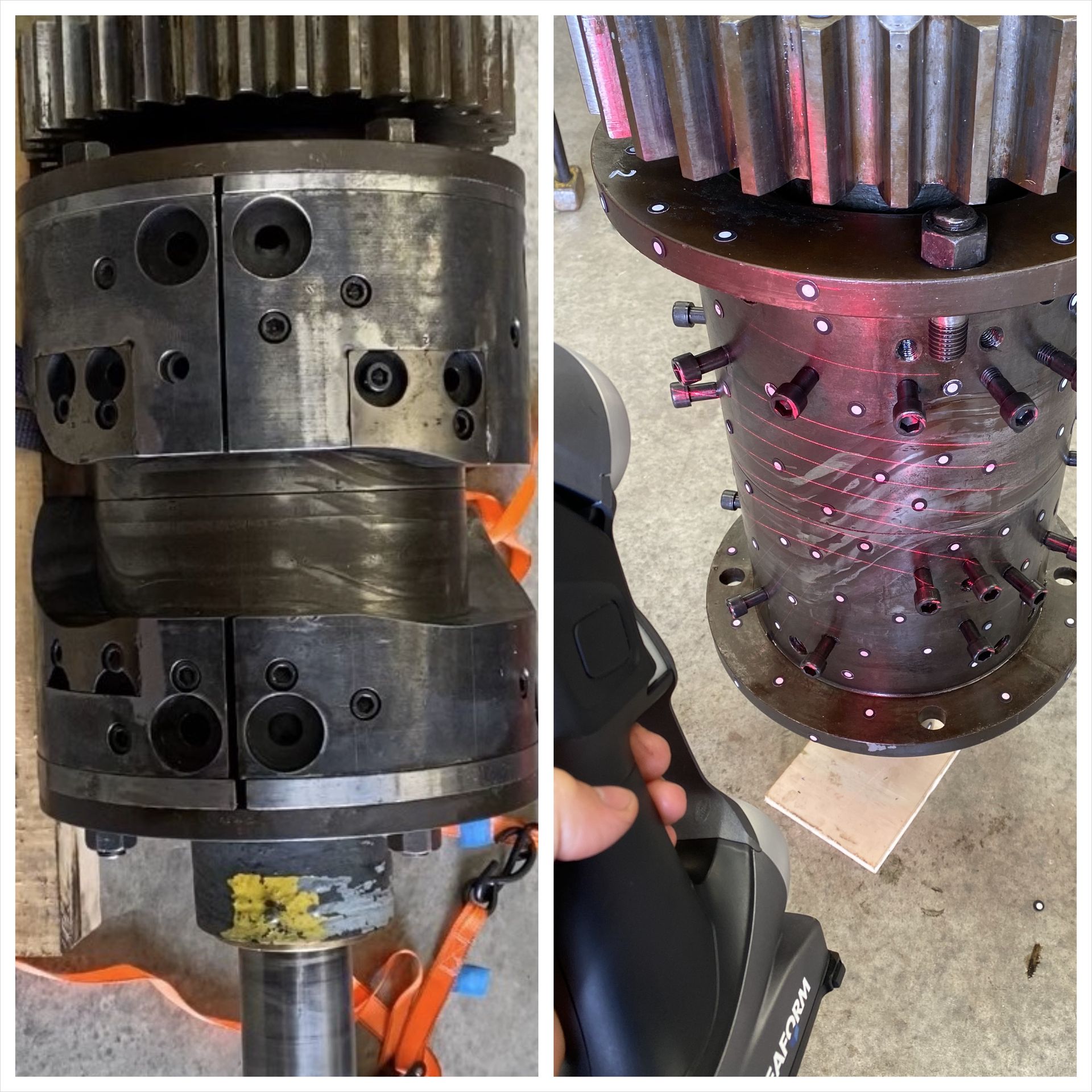
Step 1 - Data Acquisition
The part must be Prepared, Cleaned, Positioning Targets Applied and then 3D Scanned.
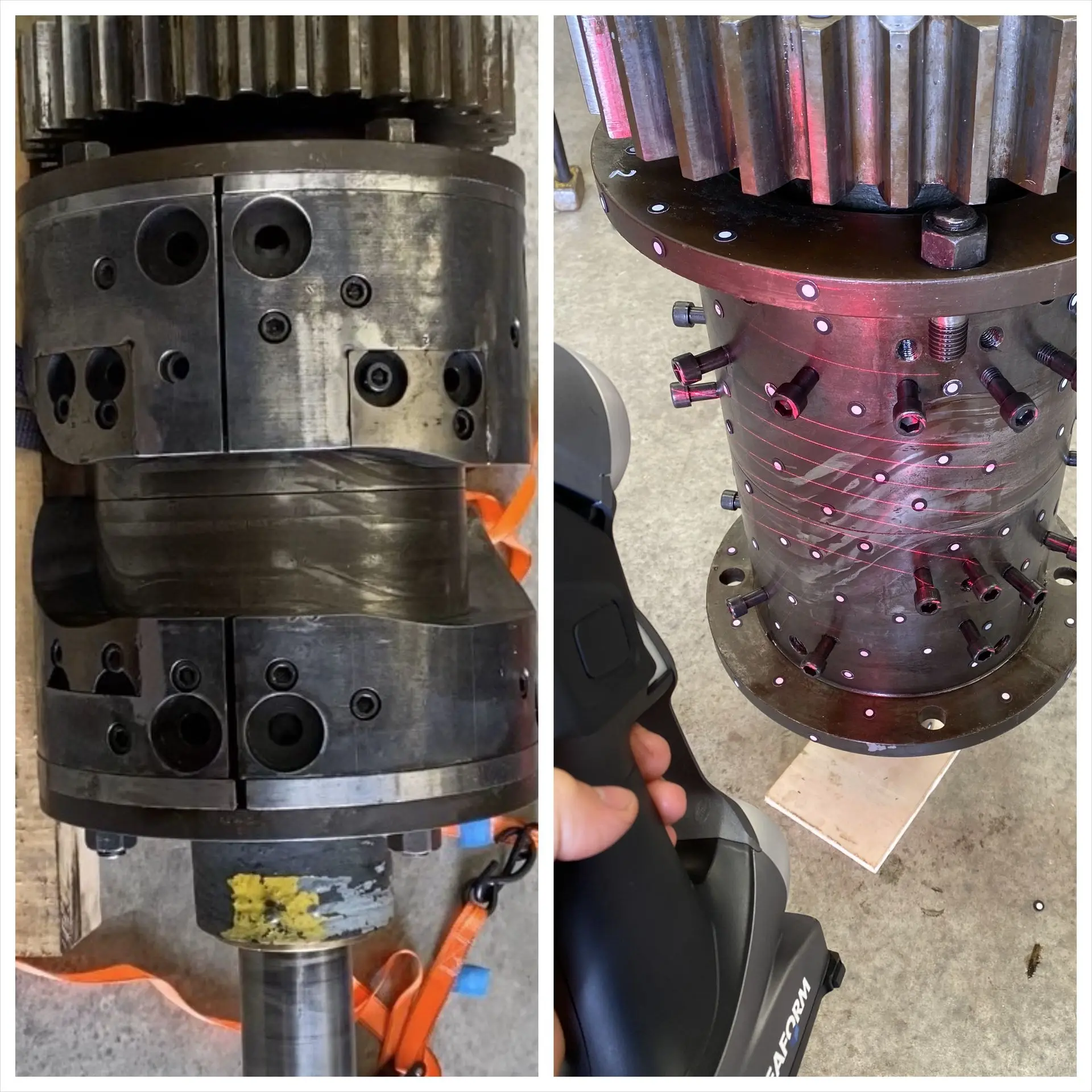
Worn Parts!
With no OEM Replacement items available or technical drawings from the supplier to remanufacture from, 3D Scanning came to the rescue.
Step 1 - Data Acquisition
The part must be Prepared, Cleaned, Positioning Targets Applied and then 3D Scanned.
From The
Physical World
To The
Digital World
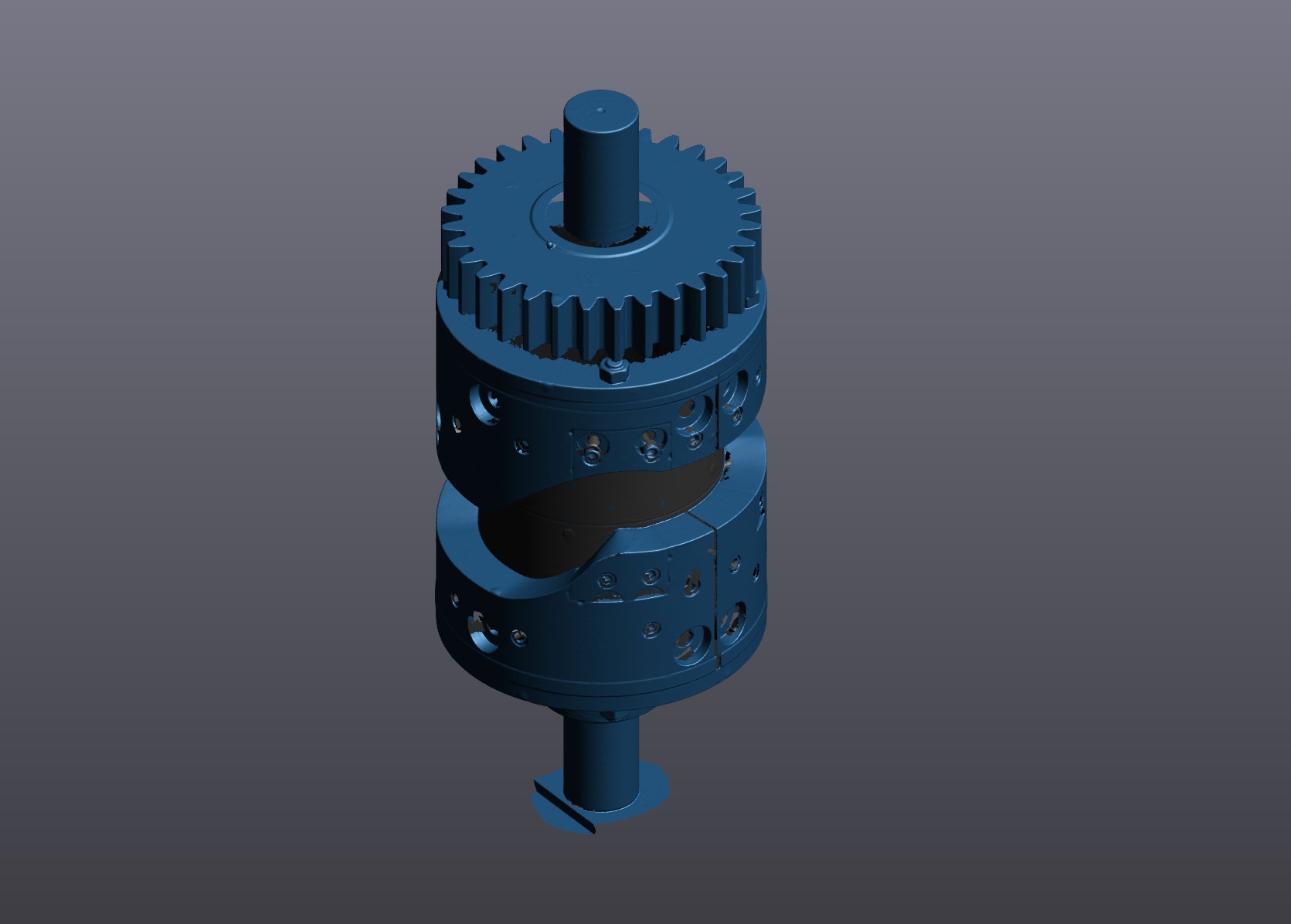
Step 2 - The object is taken from the physical world to the digital world.

From The
Physical World
To The
Digital World
Step 2 - The object is taken from the physical world to the digital world.
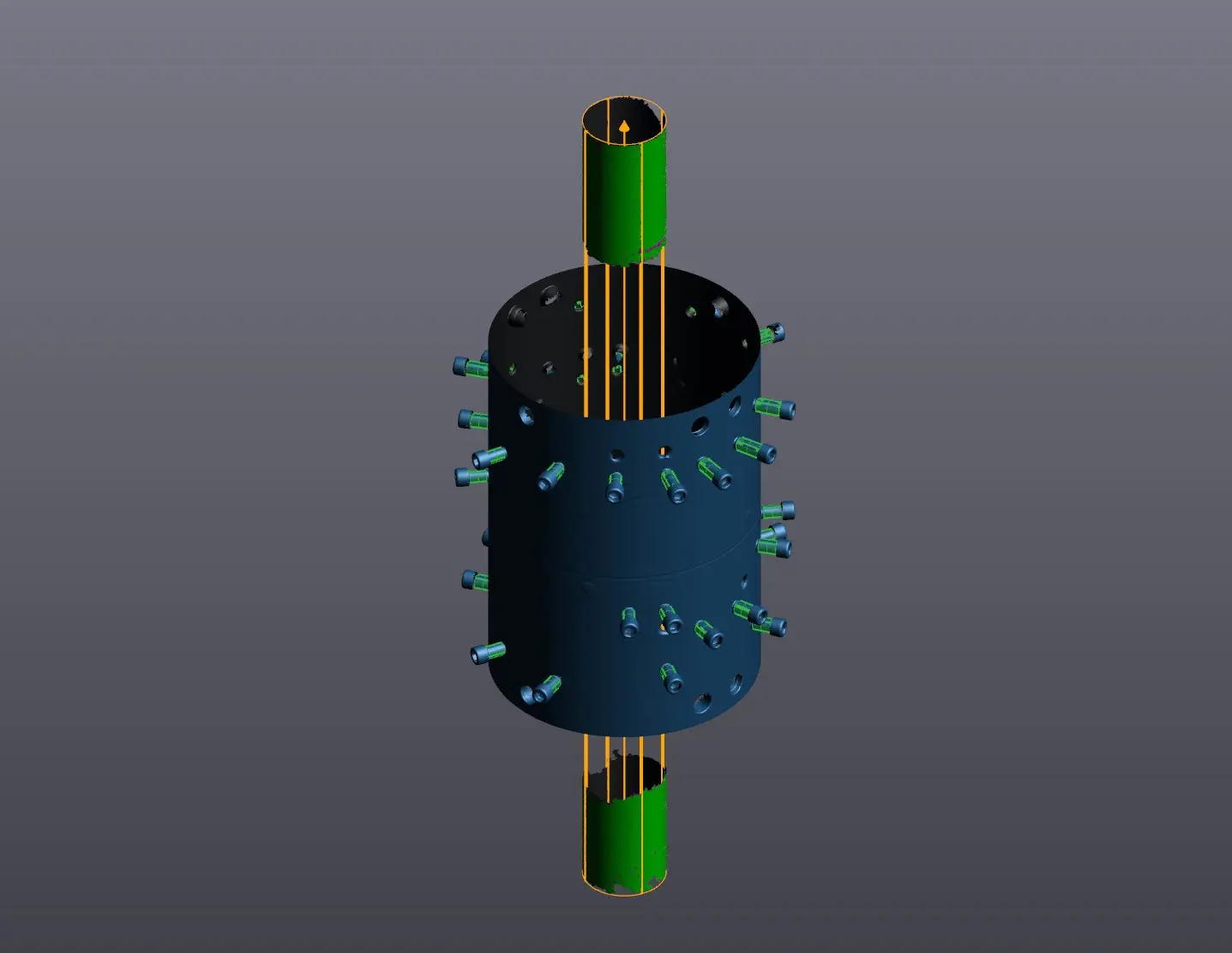
Data Extraction
Step 3 - We are now able to extract necessary information such as bolt hole axis / positions inside VX Model to reverse engineer all the individual parts.

Data Extraction
Step 3 - We are now able to extract necessary information such as bolt hole axis / positions inside VX Model to reverse engineer all the individual parts.
Reverse Engineered CAD Model
Step 4 - All parts are individually Reverse Engineered to become a Parametric/Dimensioned computer aided design 3D Model.
Displayed are the individual parts
Path Profiles/Grey
Wear Inserts/Brown
Bolt Holes/Red
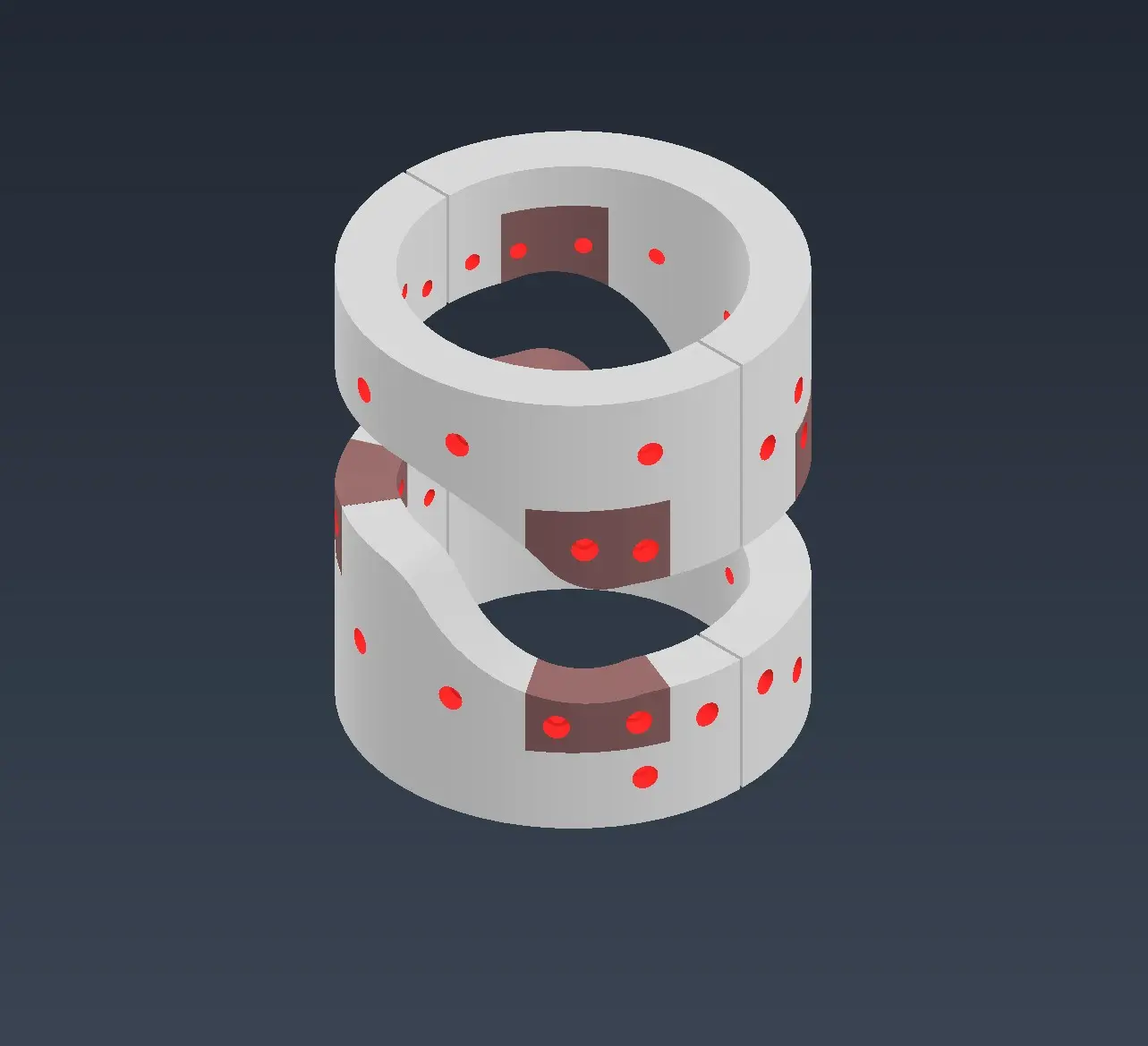

Reverse Engineered CAD Model
Step 4 - All parts are individually Reverse Engineered to become a Parametric/Dimensioned computer aided design 3D Model.
Displayed are the individual parts
Path Profiles/Grey
Wear Inserts/Brown
Bolt Holes/Red
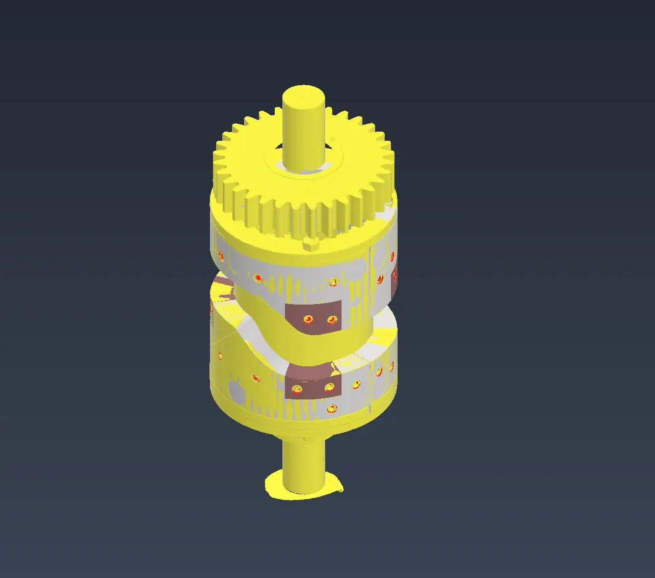
3D Scan & CAD Model
Data Overlaid
The final assembly inside CAD
Yellow / 3D Scan
Grey, Brown, Red / Reverse Engineered Parts
Step 5 - From here on we create the necessary technical drawings to remanufacture the parts.

3D Scan & CAD Model
Data Overlaid
The final assembly inside CAD
Yellow / 3D Scan
Grey, Brown, Red / Reverse Engineered Parts
Step 5 - From here on we create the necessary technical drawings to remanufacture the parts.
Want to know more about 3D Scanning?
Feel free to give us a call or email to discuss you 3D Scanning Requirements.
Contact Us
An introduction to 3D Scanning by Creaform3D
More information below on other areas 3D Scanning be Implemented through our suppliers website.
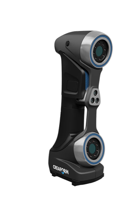
For more 3D Scanning applications check out the various use cases below through our suppliers website.

Want to know more about 3D Scanning?
Feel free to give us a call or email to discuss you 3D Scanning Requirements.
Contact Us
An introduction to 3D Scanning by Creaform3D


